Content:
Thermal Cycling and Distortion Mechanisms in Galvanizing
Hot-dip galvanizing subjects steel fabrications to substantial thermal cycling—heating from ambient temperature (typically 60°F to 80°F or 16°C to 27°C) to molten zinc bath temperature (approximately 840°F to 860°F or 449°C to 460°C), followed by cooling back to ambient conditions. This 800°F (427°C) temperature differential induces significant thermal expansion during immersion and contraction during cooling.
When fabrications possess symmetric geometry and balanced material distribution, thermal expansion forces equilibrate across the structure's neutral axes, allowing uniform dimensional change without permanent deformation. However, asymmetrical designs—those lacking balance in shape, material thickness, or weld configuration—experience unequal stress distributions during thermal cycling. These unbalanced stresses combine with residual fabrication stresses, creating conditions where distortion becomes the path of least resistance for stress relief.
The Symmetry Principle: ASTM A384 Guidance
ASTM A384, Standard Practice for Safeguarding Against Warpage and Distortion During Hot-Dip Galvanizing of Steel Assemblies, establishes the fundamental principle that warpage risk diminishes dramatically when fabrications achieve symmetry about both horizontal and vertical axes in three critical aspects:
Shape symmetry: Cross-sectional geometry balanced about centerlines
Material symmetry: Equal material thickness and mass distribution on opposing sides of neutral axes
Weld symmetry: Balanced weld placement and weld metal volume distribution
Symmetrical sections demonstrating inherent stability:
- I-beams (wide-flange sections)
- Square and rectangular hollow structural sections (HSS)
- Round pipe and tube
- Symmetrical built-up box sections
- Double angles arranged back-to-back
These shapes resist distortion because thermal expansion forces above and below the neutral axis counterbalance, preventing net bending moments or twisting forces.
Asymmetrical sections exhibiting distortion susceptibility:
- Channels (C-shapes)
- Structural tees (T-shapes)
- Angles (L-shapes)
- Custom fabricated sections with unbalanced flanges
- Camber beams with intentional curvature
- Plates with raised patterns on one surface only
Asymmetrical designs concentrate thermal stresses unevenly across the section, generating unopposed bending or twisting forces that exceed the material's elevated-temperature yield strength, causing permanent deformation.
Case Studies: Asymmetrical Design Failure Modes
Understanding specific distortion mechanisms through documented examples enables engineers to recognize and avoid problematic design configurations.
Case Study 1: Unbalanced Flange Configuration
Design characteristics:
- Web plate with top flange fabricated from structural channel
- No bottom flange to provide balancing geometry
- Single-sided material distribution relative to web neutral axis
Thermal behavior:
- Channel flange above the web experiences free thermal expansion
- No corresponding bottom flange to create counteracting expansion force
- Thermal expansion creates unbalanced moment about the web's neutral axis
- Web material lacks rigidity to resist the induced bending moment
Resulting deformation:
- Progressive twisting along the fabrication length
- Deformation follows the original rolling direction of the web plate material
- Permanent set remains after cooling due to plastic deformation exceeding yield strength at elevated temperature
Magnitude: Twisting can reach 2 to 6 inches (51 to 152 mm) of out-of-plane deviation per 10 feet (3 meters) of length for severely asymmetric sections.
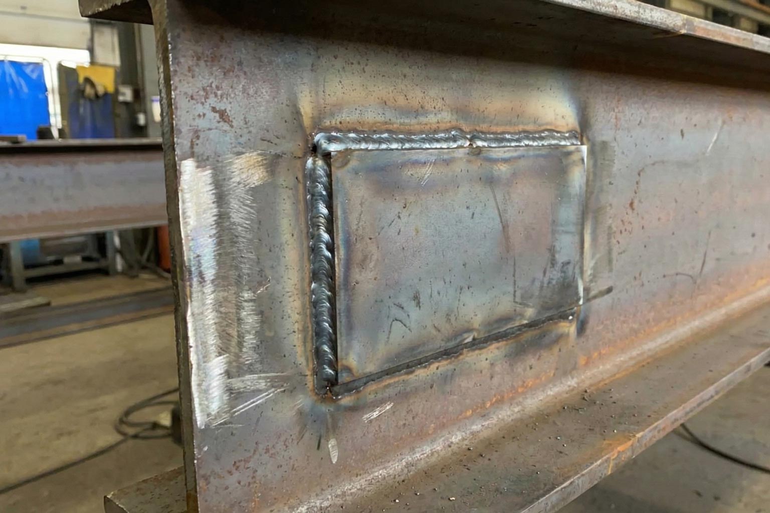
Case Study 2: Plate-to-Beam Welded Assembly
Design characteristics:
- Flat plate welded to the side of a wide-flange beam
- Continuous fillet weld joining dissimilar section geometries
- Asymmetrical mass distribution—beam possesses greater thermal mass than plate
Thermal behavior:
- Plate material heats more rapidly than the beam due to lower thermal mass
- Differential heating creates unequal thermal expansion rates
- Plate attempts to expand longitudinally faster than the beam
- Weld connection prevents independent movement, converting thermal mismatch into mechanical stress
Resulting deformation:
- Plate buckles away from the beam face at locations remote from weld constraints
- Weld joint experiences tension exceeding fracture strength
- Weld cracking initiates at high-stress concentrations (weld starts, stops, or geometric discontinuities)
- Plate exhibits wave-like buckling pattern across its surface
Engineering implication: Welded connections between members with significantly different section moduli and thermal masses create high distortion and cracking risks during thermal cycling.
Case Study 3: Constrained Thin Plate Between Thick Sections
Design characteristics:
- Thin plate (typically 3/16 inch or 5 mm) sandwiched between two thicker plates (1/2 inch or 13 mm)
- Extensive welding on both sides of the thin plate
- Asymmetrical material distribution with thin plate constrained by surrounding heavy sections
Thermal behavior:
- Thin plate heats rapidly and attempts to expand according to its thermal mass and coefficient of expansion
- Surrounding thick plates heat more slowly, creating expansion rate mismatch
- Welding on both sides completely constrains the thin plate's movement
- Thermal stress accumulates in the thin plate as it cannot expand freely
- One side of the assembly provides less constraint due to weld placement or material configuration asymmetry
Resulting deformation:
- Thin plate buckles severely—deflection up to 1 inch (25 mm) is documented in extreme cases
- Buckling relieves thermal stress through geometric displacement rather than weld failure
- Deformation remains permanent after cooling
- Correction through straightening is difficult and may induce material cracking
Prevention note: Thin sections constrained by thick sections represent one of the highest-risk configurations for galvanizing distortion.
Case Study 4: Diamond Plate (Checkered Plate) Warpage
Design characteristics:
- Flat plate with raised pattern (diamonds or checker texture) on one surface only
- Pattern creates localized thickness variation and asymmetrical mass distribution
- Additional residual stress from stamping or roll-forming pattern creation
Thermal behavior:
- Raised pattern side possesses greater surface area and thickness than the flat reverse side
- Thermal expansion differential occurs between patterned and flat surfaces
- Fabrication-induced residual stresses from cold working during pattern formation are relieved at galvanizing temperature
- Stress relief occurs non-uniformly due to asymmetrical geometry
Resulting deformation:
- Overall warping creating dish or saddle shapes across the plate surface
- Magnitude increases with thinner base plate thickness—1/8 inch (3 mm) plate exhibits more warpage than 1/4 inch (6 mm) plate
- Edge waviness and out-of-plane distortion preventing flat stacking or installation
Severity factors:
- Plate thickness: Thinner plates distort more severely
- Pattern depth: Deeper patterns create greater asymmetry
- Plate dimensions: Larger plates lack restraint to resist thermal distortion
- Material properties: Higher-strength steels retain more residual forming stress
Distortion Prevention Strategy 1: Modular Symmetric Fabrication
The most effective distortion prevention involves fabricating and galvanizing components separately in symmetric configurations, then assembling into the final asymmetric structure after coating.
Implementation methodology:
Design phase separation: Engineer the structure as discrete symmetric components that achieve required performance when assembled:
- Separate channel sections galvanized individually
- Beam and plate elements coated before joining
- Standard symmetric shapes used as building blocks
Individual galvanizing benefits:
- Each component maintains inherent geometric stability during thermal cycling
- Smaller component sizes improve handling and process control
- Coating quality optimized for each component geometry
Post-galvanizing assembly:
- Field bolting of coated components
- Field welding with subsequent weld joint coating repair per ASTM A780
- Mechanical fastening systems designed for field installation
Advantages:
- Eliminates distortion risk entirely—components never experience thermal stress in constrained asymmetric configurations
- Improved coating quality through simplified geometries
- Enhanced accessibility for coating inspection before assembly
Limitations:
- Increased fabrication cost through additional connection hardware
- Field assembly labor requirements
- Potential connection detailing complexity
- Aesthetic considerations at connection locations
Distortion Prevention Strategy 2: Temporary Symmetry Through Back-to-Back Bracing
When multiple identical asymmetric components require galvanizing, creating temporary symmetry through strategic bracing prevents distortion without design modification.
Methodology:
Component pairing: Arrange two identical asymmetric sections in mirror-image orientation (back-to-back configuration) creating a temporarily symmetric assembly.
Bracing system design:
- Install temporary spacers maintaining precise gap between paired components
- Apply external bracing members (typically angles, channels, or flat bars) spanning across paired sections
- Secure bracing with tack welds, bolts, or specialty high-temperature clamps
- Ensure bracing system provides adequate rigidity to resist thermal expansion forces without itself distorting
Galvanizing process:
- Immerse the temporarily symmetric assembly as a unit
- Symmetric configuration balances thermal expansion forces across neutral axis
- Components experience uniform heating and cooling
- Distortion forces are mutually canceled between paired sections
Post-galvanizing disassembly:
- Allow complete cooling to ambient temperature before bracing removal
- Remove external bracing members
- Separate paired components
- Touch-up bare areas at spacer contact points per ASTM A780 using zinc-rich repair materials
Critical design parameters:
Spacer sizing: Spacers must maintain adequate separation (typically 1/2 to 1 inch or 13 to 25 mm) enabling complete zinc coating penetration into the gap while providing sufficient support.
Spacer location: Position spacers to minimize coating interference on critical surfaces—typically at edges or locations that will be hidden in final assembly.
Bracing rigidity: Bracing members must possess adequate section modulus to resist the combined thermal expansion forces without bending or twisting themselves.
Attachment security: Temporary connections must withstand immersion dynamics, molten zinc forces, and thermal stresses without failing prematurely.
Economic considerations:
- Most cost-effective for production runs of identical asymmetric components
- Temporary bracing materials are reusable across multiple batches
- Touch-up time and materials add modest cost per component
- Overall cost typically lower than modular fabrication approach for repetitive components
Distortion Prevention Strategy 3: Symmetrical Redesign
When neither modular fabrication nor temporary bracing proves feasible, fundamental geometric redesign to achieve inherent symmetry eliminates distortion susceptibility.
Redesign approaches:
Add balancing material: Convert asymmetric sections to symmetric configurations:
- Add bottom flange to channel-web assembly creating I-beam geometry
- Apply matching plate to opposite beam face creating balanced assembly
- Use double angles, channels, or tees in symmetrical arrangements
Modify attachment methods: Eliminate constrained thin sections:
- Replace continuous welding with intermittent welds allowing differential expansion accommodation
- Substitute bolted connections for welded joints in high thermal stress locations
- Design slip connections accommodating thermal movement
Select alternative section types:
- Specify symmetric standard sections (I-beams, HSS) instead of asymmetric custom fabrications
- Utilize round or square tube instead of channels or angles
- Choose built-up symmetric sections rather than single asymmetric elements
Structural analysis validation:
- Verify redesigned symmetric sections provide adequate structural capacity
- Confirm deflection and stress levels meet design criteria
- Assess connection requirements for symmetric versus asymmetric designs
- Evaluate economic trade-offs between material costs and distortion prevention
Benefits:
- Permanent solution eliminating distortion risk for all future production
- No temporary bracing complexity or touch-up requirements
- Often improves structural performance through balanced geometry
- Simplified fabrication in many cases
Challenges:
- May require significant design iteration
- Potential material cost increase from added balancing elements
- Space or weight constraints may limit redesign options
- Existing design may be optimized for structural efficiency making symmetrical alternatives less economical
Fabrication Variables Influencing Distortion
Beyond overall geometry, specific fabrication practices significantly affect distortion propensity.
Residual Stress Management
Cold working effects: Forming, bending, punching, and shearing operations introduce locked-in stresses that release during galvanizing thermal cycling.
Welding sequence: Weld order and technique influence residual stress distribution:
- Balanced welding from both sides minimizes stress asymmetry
- Backstep welding sequences reduce cumulative stress buildup
- Proper weld joint design prevents excessive shrinkage forces
Stress relief heat treatment: Pre-galvanizing thermal stress relief at 1,100°F to 1,200°F (593°C to 649°C) eliminates fabrication residual stresses, though this adds process cost and may not be economically justified except for critical applications.
Material Properties
Yield strength temperature dependency: Steel yield strength decreases significantly at galvanizing temperature (approximately 50% of room-temperature values for mild steel). Lower yield strength reduces the stress threshold required to cause permanent deformation.
Coefficient of thermal expansion: While carbon steel's thermal expansion coefficient (approximately 6.5 × 10⁻⁶ in/in/°F or 11.7 × 10⁻⁶ mm/mm/°C) remains relatively constant across grades, the absolute dimensional change scales with section length—longer members experience greater expansion.
Section modulus: Thinner, more flexible sections lack rigidity to resist thermal distortion forces, while stocky, rigid sections better maintain dimensional stability.
Quality Control and Acceptance Criteria
Despite optimal design and fabrication practices, some distortion may occur in asymmetric sections. Establishing realistic acceptance criteria prevents disputes.
ASTM A123 provisions: Section 7.6 acknowledges that galvanized articles may exhibit some distortion, particularly for asymmetric designs, and indicates this is not cause for rejection unless the distortion renders the article unsuitable for its intended use.
Dimensional tolerance specification: Engineers should specify:
- Acceptable out-of-straightness limits (e.g., L/500 where L is member length)
- Critical versus non-critical dimensions requiring tighter control
- Flatness tolerances for plate elements
- Angular tolerances for assembled structures
Pre-galvanizing dimensional inspection: Document component dimensions before galvanizing to establish baseline conditions, enabling differentiation between fabrication-induced and galvanizing-induced distortion.
Straightening considerations: Post-galvanizing mechanical straightening is possible but requires caution:
- Excessive cold working may crack the galvanized coating
- Straightening should occur at moderate temperatures (200°F to 300°F or 93°C to 149°C) if possible to reduce coating damage risk
- Touch-up coating damaged areas per ASTM A780
Integrated Design Approach
Optimal distortion prevention integrates multiple strategies during design development:
Early consultation: Engage galvanizers during preliminary design to identify high-risk geometries before design commitment.
Hierarchy of preferences:
- Symmetrical standard sections (lowest risk)
- Modular assembly of symmetric components (low risk, higher fabrication cost)
- Temporary bracing of asymmetric sections (moderate risk, moderate additional cost)
- Asymmetric sections with controlled distortion acceptance criteria (higher risk)
Economic optimization: Balance distortion prevention costs against correction and acceptance risk:
- Minor asymmetry in non-critical applications may tolerate limited distortion
- Critical dimensional requirements justify symmetry optimization or modular approaches
- Repetitive production favors permanent design solutions over per-piece temporary measures
Documentation requirements: Fabrication drawings should clearly communicate:
- Galvanizing requirements and distortion prevention strategies
- Bracing details and removal sequences if applicable
- Dimensional tolerances and critical dimensions
- Assembly sequences for modular approaches
By systematically addressing geometric symmetry during design, implementing appropriate fabrication controls, and applying proven distortion prevention techniques, engineers and fabricators can successfully hot-dip galvanize even complex asymmetric structures while maintaining required dimensional accuracy and coating quality. Read the original AGA resource article on this topic at this link.
