Thermal Dynamics of Large Tubular Product Galvanizing
Large-diameter and thick-walled tubular steel products present unique thermal management challenges during hot-dip galvanizing. Unlike smaller sections or solid components that cool rapidly after zinc bath withdrawal, substantial tubular products retain considerable thermal energy for extended periods. This prolonged elevated temperature exposure continues metallurgical reactions between the zinc coating and steel substrate well beyond normal post-galvanizing timelines, potentially causing coating integrity issues and aesthetic anomalies. Understanding the thermal behavior of large tubular products and implementing appropriate cooling strategies ensures coating quality and appearance acceptability.
Heat Retention Mechanisms in Tubular Geometry
The cylindrical geometry of tubular products fundamentally affects heat dissipation compared to open structural shapes or solid sections. Several factors contribute to extended heat retention:
Enclosed Air Volume
The hollow interior of tubular products contains air that serves as thermal insulation rather than promoting heat dissipation. When the tube exits the 840°F molten zinc bath, the internal air rapidly heats through convection and radiation from the tube walls. This heated air becomes trapped within the enclosed volume, particularly in horizontal or near-horizontal orientations where natural convection cannot readily evacuate hot air.
Unlike open structural shapes where heated air rises away from all surfaces, tubular products contain their heated air mass, creating an internal heat reservoir that maintains elevated steel temperatures. This internal heating effect becomes more pronounced as tube diameter increases, since larger diameters contain greater air volumes relative to wall surface area.
Mass-to-Surface Area Ratio
Thick-walled tubular products possess high mass-to-surface area ratios compared to thinner sections. Greater mass stores more thermal energy, while limited surface area constrains heat dissipation pathways. The combination extends cooling duration significantly.
A tube with 1-inch wall thickness contains substantially more thermal mass than a tube with 1/4-inch walls of equivalent diameter. This additional mass requires proportionally longer cooling time to dissipate stored thermal energy through radiation and convection to ambient air.
Reduced Convective Cooling
Natural convection cooling requires temperature-driven air circulation across surfaces. For tubular exteriors, convective cooling proceeds normally. However, interior surfaces experience severely limited convection since enclosed air cannot readily circulate. The stagnant internal air quickly equilibrates with wall temperature, eliminating the temperature differential driving convective heat transfer.
This one-sided cooling effect—active convection on the exterior, minimal convection on the interior—substantially reduces overall cooling rate compared to open shapes experiencing convection on all surfaces.
Continued Coating Formation During Extended Cooling
The zinc coating on hot-dip galvanized steel is not simply molten zinc that solidifies upon bath withdrawal. Rather, the coating consists of multiple intermetallic zinc-iron alloy layers formed through solid-state diffusion reactions between zinc and iron atoms at elevated temperatures. These reactions begin during immersion in the 840°F molten zinc but continue as long as temperatures remain sufficiently elevated to support atomic diffusion.
Normal Coating Layer Development
Standard galvanizing produces a multi-layer coating structure:
Gamma Layer (Γ): The innermost layer adjacent to the steel substrate, containing approximately 75% zinc and 25% iron. This brittle, hard layer forms first during immersion.
Delta Layer (δ): Intermediate layer with approximately 90% zinc and 10% iron. This layer grows during immersion and brief initial cooling.
Zeta Layer (ζ): Contains approximately 94% zinc and 6% iron. This layer forms during the final moments of immersion and early cooling.
Eta Layer (η): The outermost layer of nearly pure zinc (approximately 99% zinc). This layer solidifies from the molten zinc adhering to the surface upon withdrawal.
In typical galvanizing of smaller sections, rapid cooling arrests intermetallic layer growth within minutes of bath withdrawal, "freezing" the coating structure in place.
Extended Reaction Time Effects
When large tubular products maintain elevated temperatures for 30 minutes or more after bath withdrawal, zinc-iron diffusion reactions continue forming additional intermetallic alloy layers. This extended reaction time can consume substantial portions of the original pure zinc eta layer, converting it to zinc-iron alloys while causing the coating to continue growing and evolving.
The prolonged high-temperature exposure enables iron atoms from the steel substrate to diffuse outward through existing alloy layers while zinc atoms diffuse inward, creating new alloy phases and thickening existing layers. This continued growth occurs unevenly depending on local temperature, steel chemistry variations, and initial coating structure.
The Kirkendall Effect and Coating Delamination
Extended high-temperature exposure during slow cooling creates conditions conducive to the Kirkendall Effect—a diffusion-related phenomenon that can cause coating layer separation and peeling.
Kirkendall Effect Mechanism
The Kirkendall Effect occurs when two dissimilar metals interdiffuse at different rates during solid-state reaction. In the zinc-iron system, zinc atoms diffuse significantly faster through the intermetallic layers than iron atoms. This unequal diffusion creates an atomic flux imbalance.
As more zinc atoms move inward toward the steel than iron atoms move outward toward the surface, a net mass flow occurs in one direction. This mass transport imbalance must be balanced by vacancy flow in the opposite direction. Vacancies—atomic-scale empty sites in the crystal lattice—migrate inward toward the steel substrate, accumulating at the original zinc-steel interface.
When vacancy concentration reaches critical levels, these atomic-scale defects coalesce into larger voids. With continued vacancy accumulation and coalescence, these voids can form continuous void planes between coating layers—typically at the gamma-delta layer interface or between the delta layer and steel substrate.
Void Plane Formation and Coating Separation
The void planes created by Kirkendall Effect vacancy accumulation represent physical discontinuities within the coating structure. These voids break metallurgical bonding between layers, reducing coating adhesion and mechanical integrity.
In severe cases, extensive void plane formation allows the outer coating layers to separate from the underlying steel or from inner coating layers. This separation manifests as coating peeling—large sections of coating detaching from the substrate, often in sheets or plates rather than the gradual surface wear characteristic of normal coating consumption.
Visual Characteristics of Kirkendall-Related Peeling
Coating failure from Kirkendall Effect exhibits distinctive features:
Sheet Peeling: Coating separates in relatively large, intact sheets rather than small flakes or powder.
Clean Separation Plane: The underside of peeled coating and exposed substrate show relatively smooth surfaces at the void plane location, contrasting with rough surfaces typical of mechanical damage.
Retained Coating Structure: Peeled coating sections maintain their multi-layer structure, indicating failure at a specific interface rather than general coating degradation.
Location Correlation: Peeling occurs most severely on the heaviest sections or largest diameter tubes where cooling was slowest and high-temperature exposure longest.
Thermal Management Strategies
Preventing Kirkendall Effect and associated coating peeling requires controlling post-galvanizing temperature exposure through accelerated cooling. Several strategies achieve rapid thermal reduction:
Quench Cooling: The Optimal Solution
Immediate water quenching after zinc bath withdrawal provides the most effective cooling method for large tubular products. Immersing or spraying the hot galvanized article with water transfers heat rapidly through forced convection and evaporative cooling, reducing temperatures below 600°F within minutes rather than the 30-60 minutes typical of air cooling.
Process Implementation:
Complete immersion quench tanks positioned adjacent to galvanizing kettles enable immediate article transfer from molten zinc to water quench. The dramatic temperature reduction arrests diffusion reactions almost instantaneously, freezing the coating structure and preventing excessive Kirkendall void formation.
Alternatively, high-volume water spray systems can deliver quench cooling for articles too large for immersion quenching or where facility layout prevents quench tank integration.
Critical Temperature Threshold:
Research and practical experience establish 600°F as the approximate threshold below which zinc-iron diffusion rates slow sufficiently to prevent problematic Kirkendall Effect development. Cooling articles to 600°F or below within 5-10 minutes of bath withdrawal provides adequate protection against coating peeling.
Quench Cooling Benefits:
- Nearly eliminates Kirkendall-related peeling risk
- Allows safe handling within minutes rather than requiring extended cooling periods
- Improves production throughput by reducing cycle time
- Provides more consistent coating appearance
Angled Air Cooling with Water Misting
When quench cooling equipment is unavailable or impractical, modified air cooling procedures can reduce—though not entirely eliminate—extended temperature exposure risks:
Steep Angle Positioning:
Immediately after bath withdrawal, position tubular articles at steep angles approaching vertical. This orientation enables hot air trapped within the tube interior to rise and escape through the upper open end while cooler ambient air enters through the lower end. Natural convection circulation gradually purges the hot internal air, improving interior surface cooling.
Horizontal positioning traps hot air within the tube length, maintaining elevated internal temperatures and dramatically extending cooling duration. The steep angle positioning provides substantial improvement over horizontal cooling.
Fine Water Mist Application:
Supplementing angled air cooling with fine water mist spray accelerates external surface cooling. The mist application must balance cooling effectiveness against appearance considerations:
Optimal Mist Characteristics:
- Very fine droplet size (true mist rather than coarse spray)
- Uniform application across all surfaces
- Brief application periods alternating with air cooling to avoid excessive water accumulation
Application Technique:
Apply water mist in short 2-3 second bursts, allowing time between applications for surface drying and heat dissipation. This intermittent approach cools effectively while minimizing the aesthetic issues associated with continuous water application.
Avoid Coarse Sprays:
Heavy water spray or continuous wetting creates localized rapid cooling that can produce spotty appearance—areas of differential coating crystallization, uneven oxide formation, or water staining. The resulting mottled appearance may persist indefinitely.
Temperature Monitoring
Implementing thermal management strategies requires verifying when articles have cooled sufficiently for safe handling and to arrest diffusion reactions:
Infrared Temperature Measurement:
Non-contact infrared thermometers enable quick surface temperature verification without approaching hot articles. Multiple measurements at various locations confirm uniform cooling.
Temperature-Indicating Crayons:
Temperature-sensitive crayons that melt or change color at specific temperatures provide simple go/no-go verification. Crayons rated for 600°F mark the target cooling threshold.
Handling Safety:
Beyond metallurgical considerations, personnel safety requires adequate cooling before manual handling. Burns can occur from contact with galvanized surfaces exceeding 200°F. Ensure adequate cooling for both coating quality and worker safety.
Fish-Boning: Aesthetic Phenomena in Large-Diameter Tubes
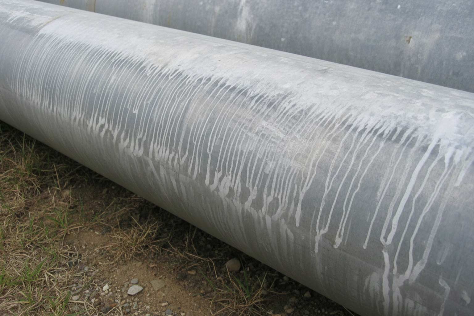
Large-diameter tubular products frequently exhibit a distinctive appearance anomaly termed "fish-boning"—a pattern resembling fish skeleton or zebra stripes distributed across the galvanized surface.
Fish-Boning Formation Mechanism
Fish-boning results from the interaction between retained heat, tube geometry, and zinc's physical properties:
Semi-Molten Zinc Behavior:
After withdrawal from the molten zinc bath, the thin layer of pure zinc on the article surface begins solidifying. However, large-diameter tubes retain sufficient internal heat to maintain portions of the surface zinc in a semi-molten or highly plastic state for extended periods.
This semi-molten zinc possesses very low viscosity and readily deforms under gravitational stress. On vertical or steeply angled tube surfaces, the semi-molten zinc begins flowing downward—similar to very slow liquid flow but occurring in material at the boundary between solid and liquid states.
Local Chemistry and Reaction Rate Variations:
Steel chemistry is never perfectly uniform across large surfaces. Minor variations in silicon content, phosphorus concentration, or other alloying elements create localized differences in zinc-iron reaction rates. These variations produce local temperature differences (reaction heat generation) and affect zinc solidification timing.
Areas experiencing faster reaction rates and higher local temperatures maintain zinc in semi-molten state longer. Areas with slower reactions and lower temperatures see zinc solidify sooner. The differential solidification creates alternating bands of mobile and stationary zinc.
Flow Pattern Development:
The semi-molten zinc flows downward under gravity until reaching cooler areas where it solidifies. This creates vertical or near-vertical flow lines alternating with stationary zones, producing the characteristic striped pattern. The pattern resembles fish bones radiating from a central spine or zebra stripes running vertically along the tube.
Texture Formation:
In addition to color variation, fish-boning creates subtle surface texture variations. Areas where zinc accumulated before final solidification exhibit slightly raised profiles compared to zones from which zinc drained away. These texture differences persist indefinitely since they represent actual zinc redistribution rather than temporary surface conditions.
Visual Characteristics
Fish-boning exhibits several distinctive features:
Regular Stripe Pattern: Generally vertical or near-vertical stripes aligned with gravity direction during cooling
Alternating Light and Dark Bands: Color variation from differences in surface texture and oxide formation patterns
Whole-Surface Distribution: Typically affects the entire tube surface rather than isolated areas
Permanent Nature: The pattern does not fade or change significantly with weathering since it represents actual zinc distribution variation
Subtle Texture: Raised ridges or depressions corresponding to zinc flow and accumulation patterns
Performance Implications
Despite its visually prominent nature, fish-boning represents purely an aesthetic concern rather than a performance deficiency:
Corrosion Protection Maintained: The zinc coating remains continuous and adequately thick across fish-boned surfaces. The slight thickness variations do not significantly affect corrosion protection life.
Mechanical Properties Unaffected: The coating's adhesion and mechanical performance remain adequate despite the appearance variations.
Coating Thickness Compliance: Fish-boned coatings typically meet ASTM thickness requirements since the overall average thickness remains adequate even with local variations.
Long-Term Stability: The fish-bone pattern remains stable during service. It does not propagate, worsen, or indicate progressive coating failure.
Acceptance Considerations
Project teams must decide whether fish-boning is acceptable based on application requirements:
Industrial Applications: Fish-boning is generally acceptable for structural steel, utility infrastructure, and industrial equipment where appearance is secondary to corrosion protection.
Architectural Applications: Projects emphasizing aesthetic appearance may find fish-boning unacceptable, particularly for prominent installations with critical viewing distances.
Specification Language: Project specifications should explicitly address fish-boning acceptance to prevent post-galvanizing disputes. Clear language establishing whether the condition is acceptable or grounds for rejection prevents ambiguity.
Relationship Between Peeling and Fish-Boning
While both phenomena relate to extended cooling times in large tubular products, peeling and fish-boning represent distinct mechanisms with different implications:
Peeling (Kirkendall Effect):
- Coating integrity failure
- Metallurgical defect from excessive diffusion
- Performance concern requiring rejection or remediation
- Prevented by adequate cooling rate
Fish-Boning:
- Appearance variation only
- Physical zinc redistribution in semi-molten state
- No performance impact
- Acceptance decision based on aesthetic requirements
Articles may exhibit one phenomenon, both, or neither depending on specific cooling conditions, steel chemistry, and tube dimensions.
Design Phase Considerations
Engineers specifying hot-dip galvanizing for large-diameter or thick-walled tubular products should address thermal management requirements during design:
Cooling Equipment Requirements
Galvanizer Capability Assessment: Verify that selected galvanizing facilities possess adequate cooling capabilities (quench systems or effective water mist equipment) for the specified tube sizes before finalizing designs.
Alternative Facilities: If preferred galvanizers lack adequate cooling infrastructure, consider alternative facilities with appropriate equipment or modify designs to use smaller tube sizes.
Appearance Specification Clarity
Fish-Boning Acceptance: Explicitly state whether fish-boning is acceptable or grounds for rejection. If unacceptable, recognize that additional cost or longer schedules may be necessary to achieve fish-bone-free appearance through enhanced cooling.
Sample Review: For appearance-critical projects, require sample galvanizing of representative tube sizes to confirm achievable appearance before bulk production commitment.
Tube Size Selection
Diameter and Wall Thickness Optimization: Engineering analysis may identify alternative tube sizes meeting structural requirements while reducing thermal management challenges. For example, using multiple smaller-diameter tubes rather than single large-diameter tubes improves cooling behavior while potentially maintaining equivalent structural performance.
Galvanizer Process Control
Galvanizing facilities processing large tubular products should implement systematic thermal management protocols:
Standard Operating Procedures
Size-Based Cooling Protocols: Establish documented cooling procedures specifying quench requirements or angled mist cooling for tube sizes exceeding defined diameter and wall thickness thresholds.
Temperature Verification: Implement mandatory temperature checking before allowing worker approach or material handling.
Quality Monitoring: Conduct periodic coating adhesion testing and visual inspection for peeling on large tubular production to verify cooling effectiveness.
Customer Communication
Pre-Production Discussion: Engage customers early regarding tube sizes, expected appearance, and cooling capabilities. Manage expectations regarding fish-boning potential for very large tubes.
Problem Notification: If coating peeling occurs despite standard cooling procedures, immediately notify customers and work collaboratively toward resolution rather than delivering defective material.
Remediation of Peeling Coatings
When inadequate cooling produces Kirkendall-related peeling despite preventive efforts, several remediation approaches may be considered:
Localized Repair
Small areas of peeling can be repaired per ASTM A780 using zinc-rich coatings or thermal spray zinc. This approach suits isolated peeling on otherwise acceptable articles.
Complete Recoating
Severely peeled articles may require complete coating removal and regalvanizing. The second galvanizing cycle, with proper cooling, should produce defect-free coating. However, double galvanizing increases cost substantially and may affect dimensional tolerances.
Acceptance with Reduced Life
If peeling is minor and the application tolerates reduced corrosion protection life, project teams may negotiate acceptance with appropriate cost adjustment reflecting reduced service life expectations.
Research and Industry Development
The galvanizing industry continues investigating improved thermal management approaches for large tubular products:
Enhanced Quench System Design: Developing quench tank configurations optimized for very large diameter tubes
Predictive Modeling: Creating computational models predicting cooling rates and Kirkendall risk for various tube dimensions and cooling methods
Alternative Alloy Systems: Investigating zinc alloy bath compositions reducing Kirkendall susceptibility
Advanced Cooling Technologies: Exploring air blast cooling, circulated internal cooling air, and other innovations improving cooling efficiency
Large-diameter and thick-walled tubular steel products present thermal management challenges during hot-dip galvanizing due to heat retention from enclosed air volumes and high mass-to-surface area ratios. Extended cooling times enable continued zinc-iron diffusion reactions that can produce Kirkendall Effect void formation, potentially causing coating peeling failures. Rapid cooling—preferably through water quenching to below 600°F within minutes of bath withdrawal—prevents problematic void development and ensures coating integrity. When quenching is unavailable, steep-angle positioning with fine water mist application provides partial protection, though risk remains elevated. The same thermal conditions producing peeling risk also generate fish-boning appearance patterns from semi-molten zinc flow during slow cooling. Unlike peeling, fish-boning represents purely aesthetic concern without performance implications, though acceptance depends on project appearance requirements. Successful galvanizing of large tubular products requires understanding thermal behavior, implementing appropriate cooling strategies, clearly specifying appearance acceptance criteria, and fostering communication among designers, galvanizers, and end users to establish realistic expectations and achieve optimal outcomes. Visit the original AGA resource article on this topic to learn more.
