Galvanizing Beyond Standard Kettle Dimensions
Hot-dip galvanizing operates as a complete immersion coating process, inherently constraining article dimensions to the physical boundaries of the zinc bath kettle. While North American galvanizing facilities typically feature kettles averaging 40 feet in length, many plants operate larger kettles measuring 50 to 60 feet long, with depths ranging from 6 to 12 feet and widths from 5 to 8 feet.
For structures exceeding these dimensions, modular design represents the preferred approach—engineering assemblies as separate components that fit within kettle constraints for individual galvanizing, then field-assembling the galvanized modules into the complete structure. However, when design requirements, structural continuity needs, or fabrication economics preclude modular approaches, progressive dipping provides an alternative methodology for coating articles larger than kettle dimensions.
Understanding the Progressive Dipping Process
Progressive dipping, also termed double dipping or sequential immersion, involves coating a single article through two separate immersion cycles. The galvanizer first lowers approximately half the article into the molten zinc bath, withdraws it after coating formation, repositions the article using different rigging points, then immerses the previously uncoated section to complete the zinc coverage.
This sequential approach effectively doubles the maximum article length or height that can be galvanized—with critical limitations and considerations that designers and fabricators must address during project planning.
Dimensional Constraints: Beyond Simple Doubling
While progressive dipping theoretically accommodates articles up to twice the kettle length, practical dimensional limitations prove more complex than simple multiplication.
Length and Height Considerations
If the kettle measures 50 feet long, progressive dipping can coat articles approaching 100 feet in length, provided one-half the article length fits completely within the kettle. The same principle applies to height—a 10-foot-deep kettle can progressively dip articles up to 20 feet tall.
Critical planning requirement: Sufficient article length must extend into the kettle during each immersion to ensure complete coating overlap, typically requiring 6 to 12 inches of overlap zone to guarantee no uncoated areas remain between dipping cycles.
Width: The Primary Constraint
Width remains non-negotiable. The article width cannot exceed the kettle width dimension, as the structure must physically fit into the bath opening during each immersion pass. Unlike length, which accommodates sequential coating, width provides no progressive dipping accommodation.
For a kettle measuring 7 feet wide, no dimension of the article can exceed approximately 6 feet 6 inches when accounting for kettle wall clearances and safe handling margins. This limitation frequently governs whether progressive dipping provides viable solution for specific projects.
Dimensional verification: Consult galvanizer kettle dimension data early in the design phase. Kettle sizes vary significantly between facilities, and identifying a galvanizer with appropriate width capacity may expand project feasibility.
Facility-Specific Handling Limitations
Theoretical dimensional capacity represents only the starting point for progressive dipping feasibility. Practical plant constraints often impose additional restrictions.
Lifting Equipment and Crane Capacity
Each galvanizing facility maintains specific crane systems with defined safe working load (SWL) limits. Article weight including rigging hardware must remain within these capacities for both dipping passes.
Weight considerations:
- Dead weight of the fabricated structure
- Molten zinc weight retained in hollow sections and internal voids after withdrawal
- Rigging hardware weight (lifting beams, chains, cables, shackles)
- Dynamic loading factors during lifting and bath immersion
Heavier structures may require specialized rigging designs or exceed facility capabilities entirely.
Plant Layout and Clearance Requirements
The galvanizer must physically maneuver the oversized article through two complete dipping cycles, including:
- Positioning over the kettle from the pre-galvanizing cleaning line
- Lowering into the bath at controlled rates
- Withdrawing at appropriate angles for drainage
- Repositioning for the second immersion pass
Building columns, overhead cranes, adjacent kettles, and other permanent plant infrastructure create clearance limitations. An article fitting kettle dimensions may still prove impossible to process if facility layout prevents proper positioning.
Essential coordination: Provide the galvanizer with detailed dimensional drawings including all projections, rigging point locations, and center of gravity calculations during pre-bid discussions. Site visits to review clearances and develop handling strategies significantly improve success probability.
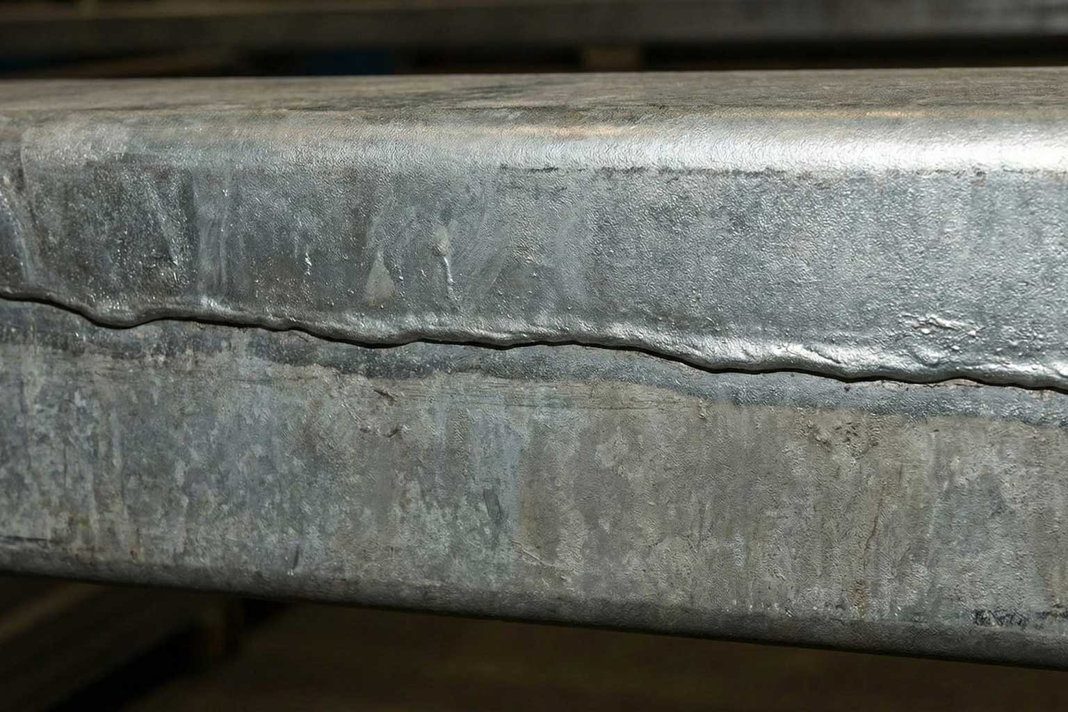
The Overlap Line: Appearance and Functional Impacts
Where the first and second immersion cycles meet, a visible overlap zone develops on the galvanized surface. This characteristic represents the most recognizable feature of progressively dipped articles.
Appearance Characteristics
The overlap line typically manifests as:
- A darker band or stripe across the article surface
- Slightly rougher texture compared to adjacent coating areas
- Increased coating thickness, often 1.5 to 2.5 times the standard coating thickness
- Width ranging from 2 to 8 inches depending on immersion overlap distance
Weathering behavior: The visual contrast between the overlap zone and surrounding coating diminishes over time through natural weathering. Within 6 to 18 months of atmospheric exposure, the overlap line becomes substantially less noticeable as the entire coating develops uniform patina.
Functional Considerations
Beyond aesthetics, overlap zone coating thickness affects:
Connection interfaces: Bolted connections, welded attachments, or mechanical fastening points located in overlap zones may experience:
- Interference from excess coating buildup preventing proper fit-up
- Need for additional bolt length to accommodate thicker coatings
- Challenges achieving specified torque values due to coating crushing
Mitigation strategies:
- Locate critical connection points outside anticipated overlap zones during design
- Specify coating thickness removal at connection surfaces through grinding or mechanical methods
- Provide dimensional tolerances accommodating thicker coatings in less critical areas
Post-galvanizing grinding: Excess coating thickness can be mechanically removed through grinding, buffing, or filing to match surrounding coating thickness, restore dimensional tolerances, or accommodate connection requirements. This localized coating removal does not compromise corrosion protection when limited to overlap zone thickness reduction rather than complete coating removal.
Distortion and Warpage: The Primary Technical Challenge
Progressive dipping introduces asymmetric thermal cycles that dramatically increase distortion risk compared to single-immersion galvanizing.
Thermal Gradient Mechanisms
During the first immersion pass:
- The immersed section reaches molten zinc temperature (approximately 840°F to 860°F or 449°C to 460°C)
- The exposed section remains at ambient temperature or slightly elevated from radiant heat
- Temperature differential across the article creates differential thermal expansion
- The hot section elongates while the cool section remains dimensionally stable
- This generates internal stresses that may exceed material yield strength
Most critical phase: The first dip produces the maximum temperature gradient and highest distortion risk. The second dip presents lower thermal differentials because the previously coated section retains residual heat from the first immersion, reducing the temperature spread across the article.
Structural Vulnerability Factors
Certain design characteristics amplify distortion susceptibility:
High length-to-thickness ratios: Long, slender members (wide-flange beams, channels, angles) lack rigidity to resist thermal stresses.
Unsupported spans: Extended distances between connection points or intermediate supports allow free deformation during thermal expansion.
Asymmetric cross-sections: Shapes with unequal flange or web dimensions expand non-uniformly, creating bending moments.
Constrained assemblies: Welded frames or truss systems cannot accommodate differential expansion through relative member movement, concentrating stresses at connection points.
Residual fabrication stresses: Cold forming, flame cutting, and welding introduce locked-in stresses that thermal cycling may release, causing unexpected deformation.
Distortion Mitigation Strategies
Successful progressive dipping requires proactive distortion control measures during design and galvanizing operations.
Design Phase Strategies
Dimensional allowances: Specify length tolerance ranges accounting for permanent thermal deformation. For critical assemblies, allowances of 1/8 to 1/4 inch per 10 feet of length provide realistic expectations.
Bracing systems: Incorporate temporary or permanent bracing members that resist thermally-induced deflection:
- Temporary bracing: Removable stiffeners attached before galvanizing and removed afterward
- Permanent bracing: Integral structural members that provide rigidity throughout service life
Connection design flexibility: Detail connections allowing post-galvanizing adjustment:
- Slotted bolt holes for alignment accommodation
- Field-drilled connection points after galvanizing
- Adjustable hardware permitting dimensional correction
Vent and drain optimization: Properly sized and positioned openings enable:
- Rapid bath immersion reducing thermal gradient exposure time
- Quick withdrawal minimizing hot soak duration
- Complete internal drainage preventing trapped zinc that adds weight and cooling differentials
Standard vent and drain sizing per American Galvanizers Association guidelines (minimum 1/2-inch diameter openings) proves insufficient for progressive dipping applications—increase opening sizes to 3/4 inch or 1 inch diameter for oversized structures.
Fabrication Considerations
Stress relief heat treatment: For critical structures, thermal stress relief at 1,100°F to 1,200°F (593°C to 649°C) before galvanizing reduces locked-in fabrication stresses, minimizing distortion tendency.
Weld joint design: Specify weld types and sequences that minimize shrinkage-induced deformation. Balanced welding from both sides of assemblies distributes thermal inputs symmetrically.
Pre-galvanizing inspection: Verify the structure meets dimensional specifications before galvanizing. Post-galvanizing correction options prove limited and expensive.
Galvanizing Process Controls
Immersion rate control: Slower immersion speeds (6 to 12 inches per minute rather than 18 to 24 inches per minute) reduce thermal shock and allow more gradual temperature equalization.
Bath temperature optimization: Operating at the lower end of acceptable zinc bath temperature ranges (840°F versus 860°F) reduces thermal gradient magnitude.
Withdrawal angle management: Controlled withdrawal angles facilitate drainage while supporting the structure against gravity-induced sagging during the high-temperature phase.
Dwell time minimization: Limiting time at temperature reduces thermal exposure duration, though adequate time must remain for complete coating formation.
Engineering Coordination Requirements
Progressive dipping success demands collaborative engineering analysis addressing thermal stress conditions.
Structural adequacy verification: The design engineer should confirm that:
- Weld joints tolerate thermal stresses at 850°F without cracking or failure
- Base metal yield strength at elevated temperature provides adequate capacity against thermally-induced stresses
- Constrained frame members accommodate differential expansion without exceeding allowable stress limits
Finite element analysis application: For critical or complex structures, thermal-structural FEA modeling predicts:
- Peak stress locations during each dipping cycle
- Anticipated permanent deformation magnitude and direction
- Optimum bracing configurations for deformation control
- Acceptable immersion depth ranges balancing coating coverage against thermal gradient severity
This analysis capability transforms progressive dipping from an uncertain process to an engineered procedure with predictable outcomes.
Decision Framework: When to Use Progressive Dipping
Progressive dipping provides optimal solutions under specific circumstances:
Favorable applications:
- Structures slightly exceeding kettle length where modular design proves impractical
- Articles requiring structural continuity precluding joints at convenient module break points
- Projects where width constraints are satisfied and distortion risks can be managed through design
- Situations where the overlap line's visual appearance is acceptable or will be obscured
Unfavorable applications:
- Structures significantly exceeding kettle length (more than 150% of kettle dimension)
- Articles with width approaching or exceeding kettle width capacity
- Thin-gauge materials highly susceptible to distortion
- Precision assemblies requiring tight dimensional tolerances after galvanizing
- Projects where visible overlap lines create aesthetic concerns in prominent locations
Always consider modular alternatives first. Properly designed modular assemblies typically deliver superior dimensional control, more uniform coating appearance, and reduced technical risk compared to progressive dipping.
Planning Timeline and Communication
Successful progressive dipping execution requires extended planning periods and enhanced communication:
Six months before galvanizing:
- Identify potential progressive dipping requirements
- Consult multiple galvanizers regarding kettle dimensions and handling capabilities
- Begin distortion analysis and bracing design
Three months before galvanizing:
- Finalize galvanizer selection
- Complete detailed rigging plans with galvanizer input
- Establish acceptance criteria for dimensional variation
- Develop contingency plans for excessive distortion
One month before galvanizing:
- Conduct pre-galvanizing dimensional inspection
- Verify vent and drain provisions meet progressive dipping requirements
- Review surface preparation and coating thickness expectations
This proactive timeline enables identification and resolution of potential issues before fabrication commitment, reducing costly modifications or project delays. The original AGA resource on Considerations for Progressive Dipping contains further information.
