The Flotation Challenge in Complex Tubular Assemblies
Tubular steel fabrications containing multiple parallel horizontal components—such as multi-rail handrail systems, architectural railing assemblies, and complex pipework configurations—present unique challenges during hot-dip galvanizing. When inadequately vented, these structures can develop sufficient buoyancy to float within the molten zinc bath, creating serious safety hazards, processing complications, and quality deficiencies. Understanding the physics of flotation, implementing proper venting design, and following established industry standards ensures successful galvanizing of complex tubular assemblies.
Understanding Flotation Physics
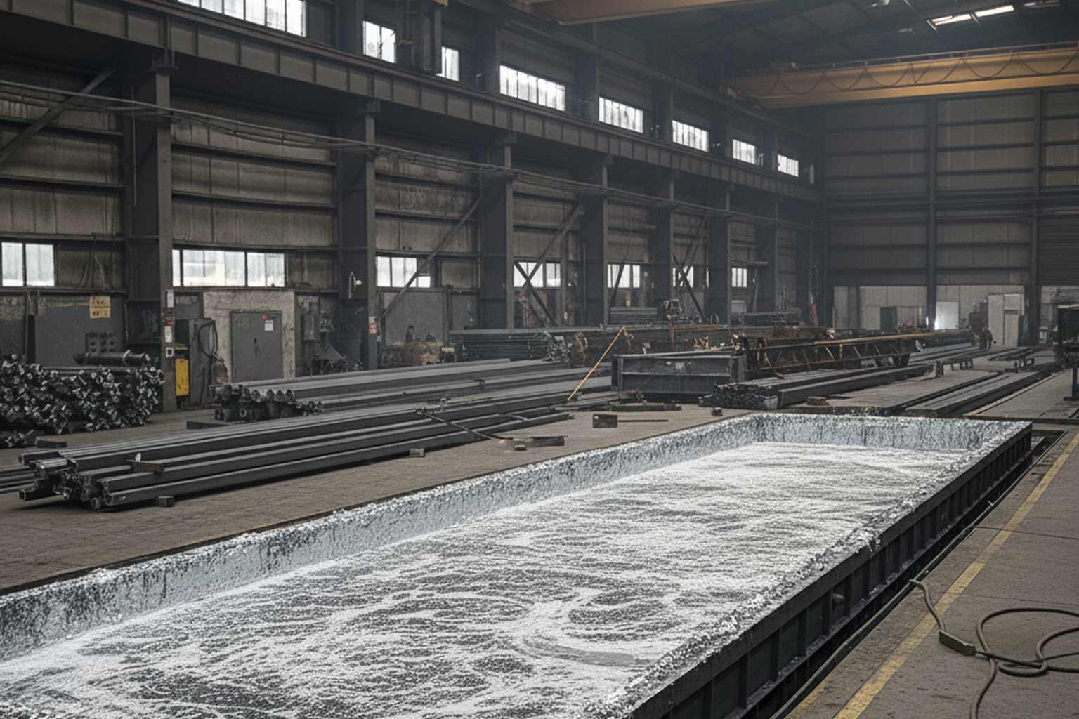
The phenomenon of floating fabrications during hot-dip galvanizing stems from basic principles of buoyancy and fluid mechanics. Molten zinc possesses a density of approximately 6.6 grams per cubic centimeter (410 pounds per cubic foot) at typical galvanizing temperatures of 820-850°F. This high density—roughly 8.5 times that of water—creates substantial buoyant forces on immersed objects.
Buoyancy Calculation
According to Archimedes' principle, an object immersed in fluid experiences an upward buoyant force equal to the weight of the displaced fluid. For steel structures immersed in molten zinc:
Buoyant Force = Volume of Zinc Displaced × Density of Molten Zinc × Gravitational Acceleration
Steel's density of approximately 7.85 grams per cubic centimeter exceeds molten zinc's density only slightly—providing minimal downward force margin for solid steel components. However, when fabrications contain enclosed hollow volumes, the effective density decreases dramatically.
The Trapped Air Effect
Tubular components and enclosed hollow sections contain air at atmospheric pressure before immersion. When submerged in molten zinc, this trapped air becomes pressurized as it heats to galvanizing temperature, but if unable to escape due to inadequate venting, it maintains internal volume against the external zinc pressure.
The trapped air volume contributes negligible weight while displacing significant zinc volume. This reduces the fabrication's effective density below that of molten zinc, generating net upward buoyant force. The problem intensifies as the number of parallel tubular components increases—each contributing additional trapped air volume while adding relatively little weight.
Critical Threshold: Five or More Parallel Components
Industry experience identifies fabrications containing five or more horizontal tubular rails or parallel components as particularly susceptible to flotation issues. This threshold reflects the cumulative buoyancy effect:
Single or Double Rails: Minimal trapped air volume relative to total fabrication weight. Standard venting typically provides adequate zinc access and air escape.
Three or Four Rails: Moderate buoyancy that standard venting may address depending on component dimensions and overall assembly configuration.
Five or More Rails: Trapped air volume often exceeds the threshold where standard vent holes provide sufficient gas escape. Additional venting becomes essential to prevent flotation.
These thresholds represent general guidelines rather than absolute limits. Actual flotation risk depends on multiple variables including tube diameter, wall thickness, overall assembly dimensions, connection details, and lifting orientation during galvanizing.
Consequences of Inadequate Venting
Floating fabrications during galvanizing create cascading problems affecting safety, quality, and efficiency:
Safety Hazards
Uncontrolled Movement: Buoyant structures may drift unpredictably within the kettle, potentially contacting kettle walls, heating elements, or other immersed articles.
Handling Difficulties: Operators cannot safely control floating articles using standard rigging and handling techniques. The upward buoyant force opposes lifting crane tension, creating unpredictable load dynamics.
Splash Risk: Rapid emergence of buoyant articles from the zinc bath surface can cause dangerous molten metal splashing, threatening personnel with severe burns.
Submersion Challenges: Maintaining proper immersion depth for floating articles requires improvised techniques that compromise normal safety protocols.
Quality Deficiencies
Incomplete Coating Coverage: Floating articles may not achieve full immersion, leaving portions above the zinc surface uncoated or inadequately coated.
Air Lock Formation: Trapped air pockets prevent molten zinc access to interior surfaces, creating uncoated zones within hollow sections.
Uneven Coating Distribution: Turbulent zinc flow around improperly vented assemblies produces coating thickness variations and appearance irregularities.
Dross Entrainment: Extended processing time and unusual handling increase the probability of bottom dross contamination adhering to the galvanized surface.
Processing Inefficiencies
Extended Cycle Time: Managing floating articles requires additional time for submersion attempts, extended immersion duration to ensure adequate coating, and careful extraction procedures.
Reduced Throughput: Processing difficulties limit the galvanizer's ability to maintain normal production schedules, affecting project delivery timelines.
Equipment Strain: Unconventional handling techniques stress overhead cranes, rigging equipment, and lifting attachments beyond normal operating parameters.
ASTM A385 Venting Requirements
ASTM A385, "Standard Practice for Providing High-Quality Zinc Coatings (Hot-Dip)," establishes comprehensive guidance for designing fabrications to optimize hot-dip galvanizing outcomes. The 2020 revision includes specific provisions addressing venting requirements for multi-component tubular assemblies.
Enhanced Venting for Multi-Rail Assemblies
For fabrications containing five or more parallel horizontal rails, ASTM A385 prescribes enhanced venting beyond standard single-hole-per-tube requirements. The standard's provisions address both external venting at tube ends and internal venting at connection points.
Internal Intersection Venting
The most critical venting specification addresses internal intersections where horizontal rails connect to vertical posts or mounting brackets:
Dual Hole Requirement: Each internal intersection—defined as the junction between a horizontal rail and a supporting vertical member—requires two vent holes positioned 180 degrees apart.
Proximity to Weld: Vent holes must be placed as close as possible to the weld joint, with the hole edge positioned less than 0.5 inches (12 millimeters) from the weld bead edge. This proximity ensures effective venting of the entire hollow section perimeter.
Minimum Diameter: Each vent hole shall measure not less than 3/8 inch (9.5 millimeters) in diameter to provide adequate cross-sectional area for air escape and zinc entry during galvanizing.
Positional Relationship: The two holes at each intersection must be 180 degrees apart—positioned on opposite sides of the tubular component. This symmetrical placement ensures that regardless of immersion orientation, at least one vent hole occupies the uppermost position where trapped air naturally accumulates.
External Visibility Requirement
All vent holes must be visible from the exterior of the assembly before galvanizing. This verification requirement enables:
- Visual confirmation by galvanizing facility personnel that adequate venting exists
- Pre-galvanizing detection of fabrication errors or omissions
- Quality assurance documentation through photographic records
- Communication between fabricators and galvanizers regarding venting adequacy
Internal vent holes accessible only through disassembly or inspection ports fail to meet this requirement.
End Section Venting
Tubular components at assembly ends or similar terminal sections require dedicated venting:
Minimum Diameter: End section vent holes shall measure at least 1/2 inch (12.7 millimeters) in diameter—larger than internal intersection vents to accommodate the full cross-sectional drainage needs.
Optional Consideration: End venting may be deemed optional based on two factors:
- Lifting Orientation: If the fabrication's galvanizing orientation positions tube ends naturally upward or downward, allowing gravity-assisted drainage, dedicated end holes may be unnecessary.
- Quality Enhancement: End venting may still be specified to achieve superior coating quality even when technically optional for basic drainage.
Field Assembly Provisions
Design details that obstruct the natural openings of vertical tubular members—such as mounting brackets, reinforcing plates, or connection hardware—must be attached after galvanizing completion. Pre-galvanizing installation of such elements can trap air or molten zinc within vertical sections, causing quality issues or safety hazards.
Physics of Effective Venting
Understanding how vent holes function during galvanizing clarifies the rationale behind specific placement and sizing requirements:
Air Escape Pathways
When a tubular assembly enters the molten zinc bath, air trapped within hollow sections heats rapidly, expanding and creating internal pressure. Vent holes provide escape pathways allowing pressurized air to evacuate as molten zinc seeks to occupy the internal volume.
The effectiveness of this air escape depends on vent hole position relative to trapped air accumulation zones. Air, being less dense than zinc, rises to the highest point within each hollow section. Vent holes positioned at or near these high points enable efficient air release.
Zinc Entry Requirements
Simultaneously with air escape, molten zinc must enter hollow sections to coat interior surfaces. This zinc entry requires adequate vent hole sizing—too small, and viscous molten zinc cannot flow efficiently; too large, and excessive zinc draining during withdrawal creates coating thickness variations.
The specified minimum diameters (3/8 inch for intersections, 1/2 inch for end sections) represent optimized compromises between air evacuation efficiency and zinc flow control.
The 180-Degree Separation Principle
Positioning two vent holes 180 degrees apart at each intersection ensures functional venting regardless of immersion angle. During galvanizing, fabrications may be oriented at various angles to optimize drainage, minimize distortion, or accommodate kettle geometry.
With diametrically opposed vent holes, at least one hole invariably occupies an elevated position where trapped air concentrates, while the opposite hole positions lower to facilitate zinc entry. This redundancy proves essential for complex assemblies where immersion angle optimization must balance multiple competing factors.
Design Implementation Guidelines
Successfully implementing enhanced venting requires attention to several practical fabrication considerations:
Hole Placement During Fabrication
Pre-Welding vs. Post-Welding: Drilling vent holes before welding simplifies positioning and ensures hole accessibility. However, post-welding drilling may better accommodate actual weld bead locations and ensures holes achieve the specified proximity to welds.
Weld Heat Affected Zone: Avoid drilling through the weld bead itself, as this may compromise weld integrity. Position holes adjacent to the weld within the specified 0.5-inch proximity while remaining in unaffected parent metal.
Deburring Requirements: All drilled holes require deburring to remove sharp edges and burrs. Sharp edges can trap flux during pretreatment or cause coating irregularities during zinc withdrawal.
Hole Marking and Documentation
Fabrication Drawings: Show all vent hole locations, diameters, and special requirements on fabrication drawings with clear dimensional references.
Inspection Verification: Include vent hole verification in fabrication quality control procedures with documented confirmation that all required holes are present and properly sized.
Galvanizer Communication: Provide fabrication drawings to the galvanizing facility before processing to enable review of venting adequacy and identification of potential issues.
Design Optimization
Minimize Hollow Volumes: Where structurally acceptable, consider design alternatives reducing enclosed air volume—such as using fewer but larger-diameter tubes rather than many small-diameter tubes.
Strategic Open Ends: Orient designs to maximize naturally open tube ends during galvanizing, reducing reliance on drilled vent holes.
Connection Detail Selection: Choose connection methods that inherently provide venting, such as gapped plug welds or intermittent welds with unwelded zones serving as vent paths.
Post-Galvanizing Hole Management
Vent and drain holes serve critical process functions during galvanizing but may present aesthetic or functional concerns for the completed structure:
Aesthetic Considerations
Applications emphasizing appearance—particularly architectural railings, decorative metalwork, and interior installations—may require concealing vent holes to achieve desired visual quality.
Functional Requirements
Certain applications may demand sealed tubular sections for structural performance, exclusion of moisture or contaminants, or compliance with specific design requirements.
Plugging Solutions
Zinc or Aluminum Plugs: Tapered metallic plugs manufactured from zinc or aluminum alloys provide the most common post-galvanizing hole sealing method. These plugs offer several advantages:
- Corrosion Compatibility: Zinc plugs maintain galvanic compatibility with the galvanized coating, avoiding accelerated corrosion at dissimilar metal interfaces.
- Mechanical Installation: Tapered design enables simple hammer-driven installation without threading or adhesives.
- Flush Finishing: After installation, plugs can be filed or ground flush with surrounding surfaces for minimal visual impact.
- Field Installation: Plugs install readily at the construction site without specialized equipment.
Alternative Sealing Methods:
- Zinc-Rich Putty: Malleable zinc-based compounds can fill holes while maintaining corrosion protection compatibility.
- Welding: Small holes can be seal welded closed, though this requires field welding capability and subsequent touch-up of the weld zone with zinc-rich coating.
- Threaded Plugs: Tapping vent holes and installing threaded fasteners provides removable sealing for applications requiring periodic internal inspection.
The selection among these methods depends on aesthetic requirements, accessibility, installation constraints, and project budget.
Special Considerations for Complex Geometries
Architectural Railing Systems
Architectural railings often combine aesthetic demands with the structural reality of multi-rail configurations. Design strategies for these applications include:
Modular Design: Breaking complex railing runs into smaller modules reduces the number of parallel rails per galvanized piece, potentially avoiding the five-rail threshold requiring enhanced venting.
Hybrid Systems: Combining galvanized structural rails with non-galvanized decorative infill elements (attached after galvanizing) reduces hollow volume while maintaining design intent.
Strategic Component Selection: Using solid bar elements for some rails rather than hollow tubes decreases overall buoyancy risk.
Industrial Pipework Assemblies
Complex process piping manifolds, cooling system headers, and utility distribution assemblies frequently exceed five parallel components while incorporating intricate connection geometries:
3D Flow Analysis: For highly complex assemblies, mental visualization of air escape and zinc flow paths during various immersion angles helps optimize vent hole placement.
Oversized Venting: Consider specifying vent holes larger than minimum requirements for complex geometries where drainage paths span long distances or navigate multiple directional changes.
Pre-Galvanizing Flow Testing: For critical applications, fabricators may conduct water flow tests of completed assemblies to verify adequate venting and drainage before galvanizing.
Collaboration Among Stakeholders
Successful galvanizing of complex tubular assemblies requires coordination among designers, fabricators, and galvanizers:
Design Phase Engagement
Engineers and architects should:
- Consult galvanizing facilities during design development to review venting adequacy
- Incorporate ASTM A385 venting requirements into fabrication specifications
- Consider galvanizing process constraints when establishing aesthetic and functional requirements
Fabrication Phase Verification
Fabricators should:
- Implement quality control procedures verifying vent hole presence, positioning, and sizing
- Maintain photographic documentation of vent holes before galvanizing
- Communicate with galvanizers regarding unusual geometries or potential processing concerns
Galvanizing Phase Assessment
Galvanizers should:
- Review fabrication drawings and inspect physical articles before processing
- Communicate concerns about venting adequacy to fabricators and project managers
- Document any processing difficulties or quality issues related to inadequate venting
This collaborative approach identifies and resolves potential issues before they impact project schedules or quality outcomes.
Quality Assurance and Acceptance Criteria
Establishing clear quality expectations for venting and resulting coating quality prevents post-galvanizing disputes:
Specification Requirements: Project specifications should explicitly reference ASTM A385 venting requirements for applicable assemblies and clarify whether vent hole plugging is required or optional.
Inspection Protocols: Define pre-galvanizing inspection procedures verifying vent hole compliance with drawings and standards.
Coating Acceptance Criteria: Establish coating thickness and appearance standards considering the inherent challenges of coating complex tubular assemblies even with proper venting.
Documentation Requirements: Specify what photographic or written documentation must accompany galvanized deliveries to demonstrate venting compliance.
Economic Implications
Enhanced venting requirements affect project economics in several ways:
Fabrication Costs: Additional drilling operations increase fabrication labor and time. However, these costs pale compared to potential rework expenses from inadequate venting.
Processing Costs: Properly vented assemblies galvanize efficiently, potentially qualifying for standard pricing. Inadequately vented assemblies may incur additional processing charges for extended handling time and special techniques.
Quality Risk Mitigation: Investment in proper venting design and implementation eliminates costly rework, project delays, and potential rejection of inadequately coated products.
Life-Cycle Value: Successful galvanizing providing complete coating coverage delivers maximum corrosion protection and service life, optimizing long-term project value.
Complex tubular assemblies containing multiple parallel components require enhanced venting design to prevent flotation during hot-dip galvanizing. The physics of buoyancy in dense molten zinc creates substantial upward forces on inadequately vented hollow structures, causing safety hazards, quality deficiencies, and processing complications. ASTM A385 provides specific venting requirements for multi-rail assemblies including dual vent holes positioned 180 degrees apart at internal intersections, proper proximity to weld joints, and minimum hole sizing to ensure adequate air escape and zinc flow. Successful implementation requires collaborative engagement among designers, fabricators, and galvanizers during all project phases, with clear communication of venting requirements, verification of proper execution, and establishment of realistic quality expectations. Post-galvanizing hole plugging options address aesthetic or functional requirements for sealed tubular sections while maintaining the corrosion protection benefits of properly vented galvanizing. By understanding flotation physics, implementing industry standards, and fostering stakeholder collaboration, engineers can confidently specify hot-dip galvanizing for complex tubular assemblies while achieving superior coating quality and project outcomes. Refer to the original AGA resource on this topic for more information.
